Wire Size Calculator
Calculate the minimum size of a wire or conductor needed for a circuit, or calculate the dimensions of the wire, including the diameter, cross-sectional area, and resistance given its gauge.
Results: Minimum Wire Size
Expected Voltage Drop
| inches: | |
| millimeters: |
Cross-sectional Area
| kcmil: | |
| square inches: | |
| square millimeters: |
Cross-sectional Area
| kcmil: | |
| square inches: | |
| square millimeters: |
On this page:

Joe is the creator of Inch Calculator and has over 20 years of experience in engineering and construction. He holds several degrees and certifications.

Ahmed holds a Master’s degree in electrical engineering and currently works as an electrical engineer with Energy Systems Research Laboratory.
How to Calculate Wire Size
A wire gauge is a standard unit for measuring the diameter of the wire, and American Wire Gauge (AWG) is the standard used in North America for conductors in electrical systems. Depending on the application, it is essential to use conductors of the proper size for safe and reliable power delivery and to reduce the amount of voltage drop in the system.
An oversized conductor could be a waste of money, and an undersized conductor might not be able to handle the required current flows, which is why choosing the correct wire size is so important.
Minimum Wire Size Formula for Single-Phase Circuits
Use the following formula to calculate the minimum wire size for a DC or single-phase AC circuit:[1]
A(m²) = 2 × ρ(Ω·m) × L(m) × I(A) / V(V)
Where:
A = cross-sectional area in square meters
ρ = conductor resistivity in ohm-meters (Ω·m)
L = length in meters
I = current in amps
V = allowable voltage drop in volts
Thus, the minimum cross-sectional area A for a wire in square meters is equal to the product of two, the conductor resistivity ρ, its length L in meters, and the current I in amps, divided by the allowable voltage drop V in volts.
The resistivity of a copper conductor is 1.7241×10⁻⁸ Ω·m and the resistivity of an aluminum conductor is 2.6548×10⁻⁸ Ω·m.
To convert the resulting cross-sectional area to square millimeters, multiply the result by 1,000,000.
A(mm²) = (m²) × 1,000,000
For example, let’s calculate the wire size of a 100-meter-long copper wire for a single-phase circuit when it must supply 30 amps of current with a 10 V voltage drop allowed:
A(mm²) = 2 × 1.7241×10-8 Ω·m × 100 m × 30 A / 10 V × 1,000,000
A(mm²) = 10.3446×10-6 m² × 1,000,000
A(mm²) = 10.3446 mm²
By comparing the size to the list of AWG wire sizes in the chart below, we can see that a 7 AWG wire size, which has a cross-sectional area of 10.549 mm², will meet the minimum requirements for this circuit.
Note that these formulas do not account for temperature variation or any national or local electric codes, such as the National Electric Code, that might require a larger gauge conductor, depending on the application.[2] You can use our wire ampacity calculator to confirm the conductor supports the current requirements for the application.
Always consult a qualified electrical professional before installing or altering electrical wiring or components.
Minimum Wire Size Formula for Three-Phase Circuits
The formula to calculate the wire size for a three-phase AC circuit is slightly different:
A(m²) = √3 × ρ(Ω·m) × L(m) × I(A) / V(V)
The minimum cross-sectional area A for a wire in square meters is equal to the product of the square root of three, the conductor resistivity ρ, its length L in meters, and the current I in amps, divided by the allowable voltage drop V in volts.
Solving the same example as before, but for a three-phase circuit, we get:
A(mm²) = √3 × 1.7241×10-8 Ω·m × 100 m × 30 A / 10 V × 1,000,000
A(mm²) = 8.9586×10-6 m² × 1,000,000
A(mm²) = 8.9586 mm²
By comparing the size to the list of AWG wires, we can see that a 7 AWG wire size will still meet the minimum requirements for this circuit.
To find the gauge of wire required, use the chart below to find the wire gauge with the necessary cross-sectional area.
How to Calculate a Wire’s Area and Diameter
You can calculate the wire size, diameter, and cross-sectional area using the wire gauge and a few simple formulas.
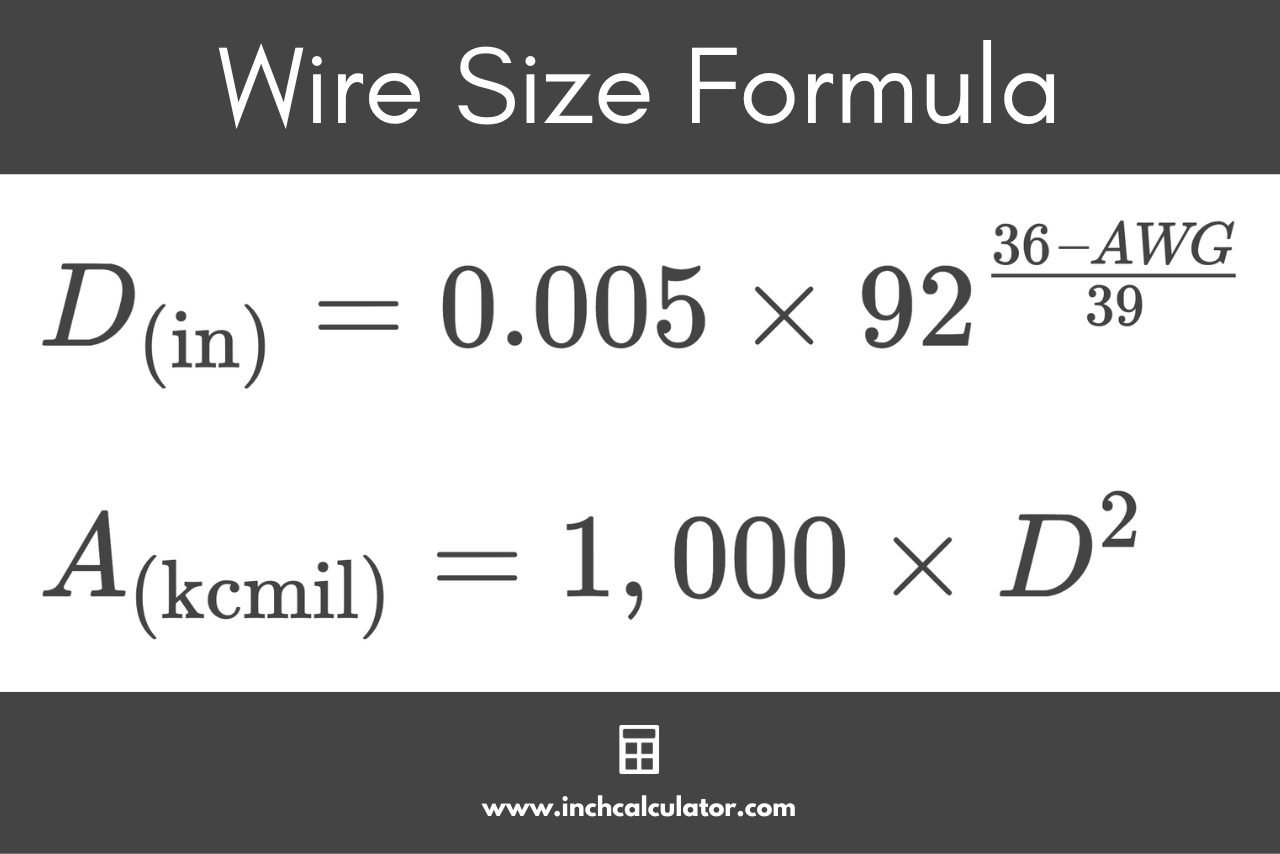
Wire Diameter Formula
The formula to find the diameter of the wire in inches is:
D(in) = 0.005 × 92(36 – AWG) ÷ 39
The formula to find the diameter of the wire in millimeters is:
D(mm) = 0.127 × 92(36 – AWG) ÷ 39
Steps to Find the Diameter of a Conductor
First – find the exponent in the equation by subtracting the wire gauge from 36 and then dividing by 39.
Finding the exponent for 00, 000, and 0000 gauge wire is slightly different. Substitute -1, -2, and -3 for the gauge in the formula above instead of the AWG value.
Second – find 92 to the power calculated in the previous step.
Third – multiply the value from the second step by either .005 inches or .127 mm to find the diameter of the wire in inches or millimeters, respectively.
Wire Cross-Sectional Area Formula
The formula to find the cross-sectional area of the wire in kilo-circular mils, or kcmil, is:
A(kcmil) = 1,000 × D(in)²
The formula to find the cross-sectional area of the wire in square millimeters is:
A(mm²) = π / 4 × D(mm)²
Steps to Find the Cross-Sectional Area of a Conductor
First – find the diameter of the wire. Use the formula above to calculate the width if the AWG is known.
Second – multiply the diameter by 1,000 to find the area in kcmil or by (3.1415 ÷ 4) to calculate square millimeters.
Wire Gauge Chart
| AWG | Diameter | Cross-Sectional Area | Resistance | |||
|---|---|---|---|---|---|---|
| (inches) | (mm) | (kcmil) | (mm²) | Ohms per 1,000 ft | Ohms per 1,000 m | |
| 0000 (4/0) | 0.46 | 11.684 | 211.6 | 107.22 | 0.049 | 0.1608 |
| 000 (3/0) | 0.4096 | 10.405 | 167.81 | 85.029 | 0.0618 | 0.2028 |
| 00 (2/0) | 0.3648 | 9.266 | 133.08 | 67.431 | 0.0779 | 0.2557 |
| 0 (1/0) | 0.3249 | 8.251 | 105.53 | 53.475 | 0.0983 | 0.3224 |
| 1 | 0.2893 | 7.348 | 83.693 | 42.408 | 0.1239 | 0.4066 |
| 2 | 0.2576 | 6.544 | 66.371 | 33.631 | 0.1563 | 0.5127 |
| 3 | 0.2294 | 5.827 | 52.635 | 26.67 | 0.197 | 0.6464 |
| 4 | 0.2043 | 5.189 | 41.741 | 21.151 | 0.2485 | 0.8152 |
| 5 | 0.1819 | 4.621 | 33.102 | 16.773 | 0.3133 | 1.028 |
| 6 | 0.162 | 4.115 | 26.251 | 13.302 | 0.3951 | 1.296 |
| 7 | 0.1443 | 3.665 | 20.818 | 10.549 | 0.4982 | 1.634 |
| 8 | 0.1285 | 3.264 | 16.51 | 8.366 | 0.6282 | 2.061 |
| 9 | 0.1144 | 2.906 | 13.093 | 6.634 | 0.7921 | 2.599 |
| 10 | 0.1019 | 2.588 | 10.383 | 5.261 | 0.9988 | 3.277 |
| 11 | 0.0907 | 2.305 | 8.234 | 4.172 | 1.26 | 4.132 |
| 12 | 0.0808 | 2.053 | 6.53 | 3.309 | 1.588 | 5.211 |
| 13 | 0.072 | 1.828 | 5.178 | 2.624 | 2.003 | 6.571 |
| 14 | 0.0641 | 1.628 | 4.107 | 2.081 | 2.525 | 8.285 |
| 15 | 0.0571 | 1.45 | 3.257 | 1.65 | 3.184 | 10.448 |
| 16 | 0.0508 | 1.291 | 2.583 | 1.309 | 4.015 | 13.174 |
| 17 | 0.0453 | 1.15 | 2.048 | 1.038 | 5.063 | 16.612 |
| 18 | 0.0403 | 1.024 | 1.624 | 0.823 | 6.385 | 20.948 |
| 19 | 0.0359 | 0.9116 | 1.288 | 0.6527 | 8.051 | 26.415 |
| 20 | 0.032 | 0.8118 | 1.022 | 0.5176 | 10.152 | 33.308 |
| 21 | 0.0285 | 0.7229 | 0.8101 | 0.4105 | 12.802 | 42.001 |
| 22 | 0.0253 | 0.6438 | 0.6424 | 0.3255 | 16.143 | 52.962 |
| 23 | 0.0226 | 0.5733 | 0.5095 | 0.2582 | 20.356 | 66.784 |
| 24 | 0.0201 | 0.5106 | 0.404 | 0.2047 | 25.668 | 84.213 |
| 25 | 0.0179 | 0.4547 | 0.3204 | 0.1624 | 32.367 | 106.19 |
| 26 | 0.0159 | 0.4049 | 0.2541 | 0.1288 | 40.814 | 133.9 |
| 27 | 0.0142 | 0.3606 | 0.2015 | 0.1021 | 51.466 | 168.85 |
| 28 | 0.0126 | 0.3211 | 0.1598 | 0.081 | 64.897 | 212.92 |
| 29 | 0.0113 | 0.2859 | 0.1267 | 0.0642 | 81.833 | 268.48 |
| 30 | 0.01 | 0.2546 | 0.1005 | 0.0509 | 103.19 | 338.55 |
| 31 | 0.008928 | 0.2268 | 0.0797 | 0.0404 | 130.12 | 426.9 |
| 32 | 0.00795 | 0.2019 | 0.0632 | 0.032 | 164.08 | 538.32 |
| 33 | 0.00708 | 0.1798 | 0.0501 | 0.0254 | 206.9 | 678.8 |
| 34 | 0.006305 | 0.1601 | 0.0398 | 0.0201 | 260.9 | 855.96 |
| 35 | 0.005615 | 0.1426 | 0.0315 | 0.016 | 328.98 | 1,079.3 |
| 36 | 0.005 | 0.127 | 0.025 | 0.0127 | 414.84 | 1,361 |
| 37 | 0.004453 | 0.1131 | 0.0198 | 0.01 | 523.1 | 1,716.2 |
| 38 | 0.003965 | 0.1007 | 0.0157 | 0.007967 | 659.62 | 2,164.1 |
| 39 | 0.003531 | 0.0897 | 0.0125 | 0.006318 | 831.77 | 2,728.9 |
| 40 | 0.003145 | 0.0799 | 0.009888 | 0.00501 | 1,048.8 | 3,441.1 |
Also, see our electricity cost calculator or our lighting cost calculator before you plan your next electrical project.
References
- Miller, C., NFPA's Electrical References, National Fire Protection Association, 2004, Jones & Bartlett Learning, 235-238. https://www.google.com/books/edition/NFPA_s_Electrical_References/raUyIi7i-asC
- Vigstol, D., Determining Current Carrying Capacity of Conductors, National Fire Protection Association, July 21, 2021, https://www.nfpa.org/News-and-Research/Publications-and-media/Blogs-Landing-Page/NFPA-Today/Blog-Posts/2021/07/21/Determining-Current-Carrying-Capacity-of-Conductors