RLC Impedance Calculator
Use our impedance calculator to find the impedance in RLC circuits given the resistance, inductance, capacitance, and frequency of the circuit.
Calculate Impedance in an RLC Circuit
Calculate Impedance in an RL Circuit
Calculate Impedance in an RC Circuit
Calculate Impedance in an LC Circuit
Results: Impedance
| Impedance (Z): |
- mΩ
- Ω
- kΩ
|
| Inductive Reactance (XL): |
- mΩ
- Ω
- kΩ
|
| Capacitive Reactance (XC): |
- mΩ
- Ω
- kΩ
|
| Angular Frequency (ω): |
- rad/s
|
On this page:

Joe is the creator of Inch Calculator and has over 20 years of experience in engineering and construction. He holds several degrees and certifications.
How to Calculate the Impedance in an RLC Circuit
Calculating the impedance of RLC circuits forms a fundamental aspect of understanding how circuits behave in the presence of alternating current (AC). An RLC circuit is a circuit with a resistor, inductor, and a capacitor in series or parallel.
Impedance, symbolized as Z, is a complex quantity that combines resistance R, inductance L, and capacitance C to describe a circuit’s opposition to the flow of alternating current.
Impedance in an RLC circuit varies significantly based on the configuration of the components (whether they are arranged in series or parallel) and the frequency of the input signal. This variability stems from the frequency-dependent behavior of inductors and capacitors.
Angular Frequency
Before calculating impedance, you will need to calculate the angular frequency of the alternating current. You can calculate the alternating frequency (denoted ω) using the formula:
The angular frequency ω in radians per second is equal to 2 times pi times the resonant frequency 𝑓 in hertz.
RLC Impedance Formulas
You can use one of several formulas to calculate the impedance in RLC circuits, depending on whether the components are arranged in series or parallel and which components are present.
Series RLC Circuit Impedance Formula
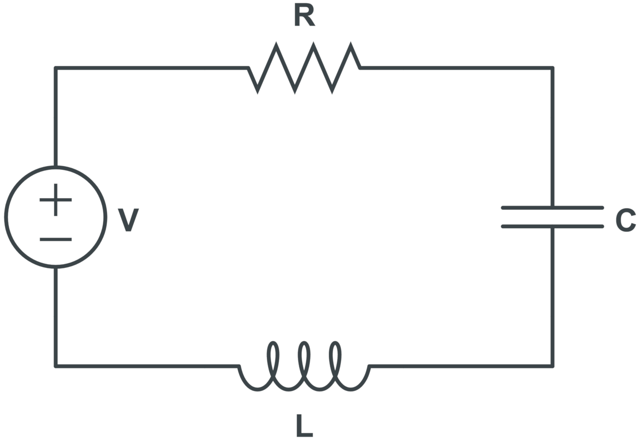
The formula to calculate the total impedance in series RLC circuits is:
Where:
Z = impedance in Ω
R = resistance in Ω
L = inductance in H
C = capacitance in F
ω = angular frequency in rad/s
The total impedance Z in Ohms for a series RLC circuit is equal to the square root of the resistance R in Ohms squared plus the inductive reactance minus the capacitive reactance squared.
The inductive reactance (XL) is equal to the angular frequency ω in radians per second times the inductance L in Henries. The capacitive reactance (XC) is equal to the reciprocal of the angular frequency ω in radians per second times the capacitance C in Farads.
Parallel RLC Circuit Impedance Formula
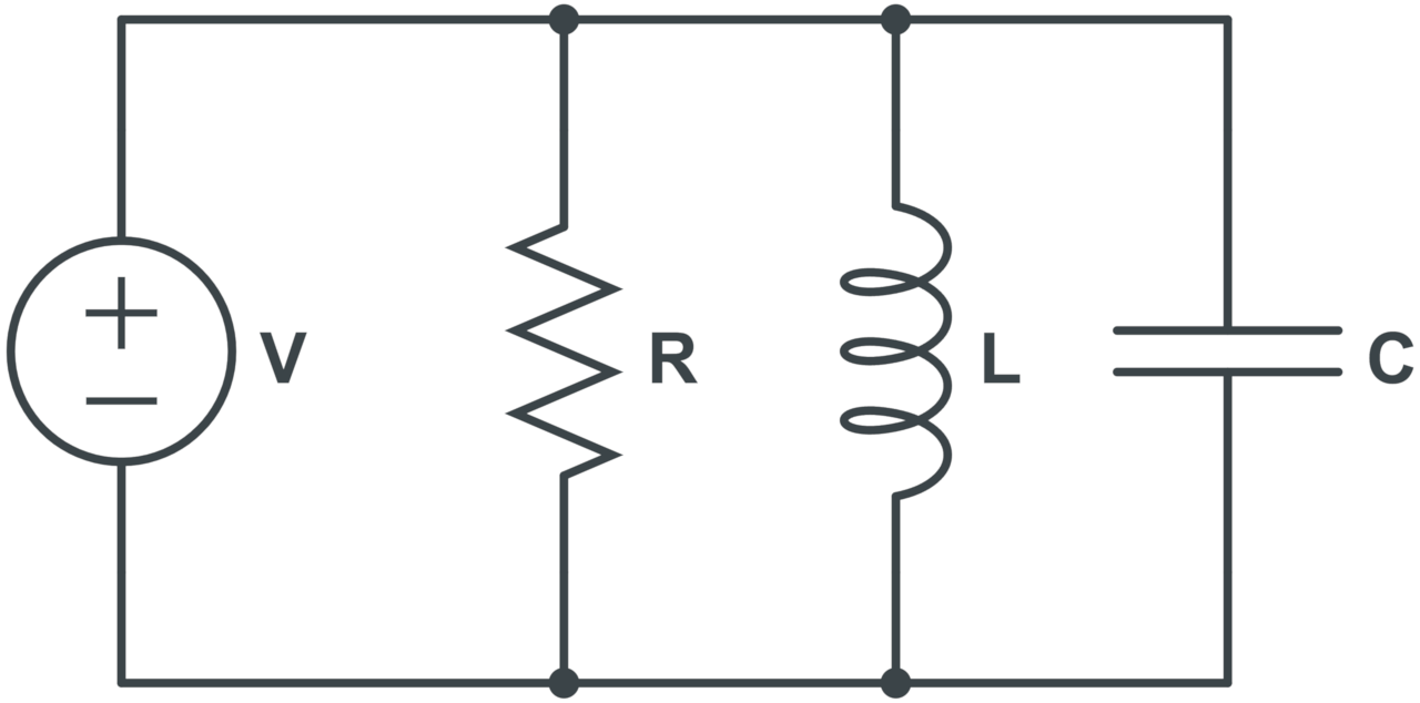
The formula to calculate the total impedance in parallel RLC circuits is:
Where:
Z = impedance in Ω
R = resistance in Ω
L = inductance in H
C = capacitance in F
ω = angular frequency in rad/s
The total impedance Z in Ohms for a parallel RLC circuit is equal to the square root of the reciprocal of the resistance R in Ohms squared plus the reciprocal of the inductive reactance minus the reciprocal of the capacitive reactance squared.
RL Impedance Formulas
RL circuits are those with a resistor and inductor that are either in series or parallel. The formulas to calculate impedance for these circuits are the same as for RLC circuits, but without consideration for the capacitive reactance.
Series RL Circuit Impedance Formula
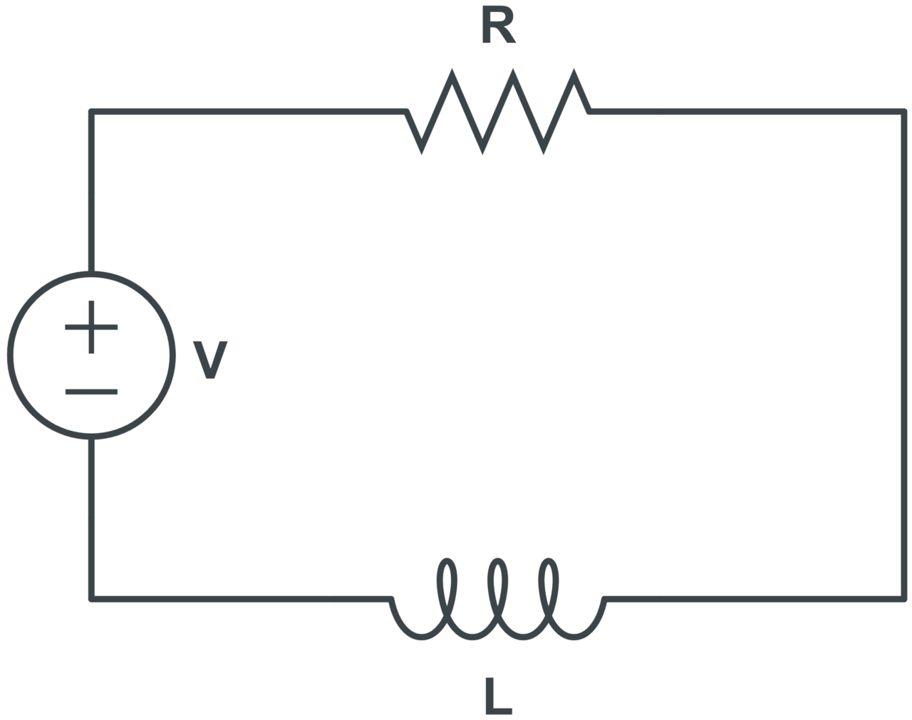
The formula to calculate the total impedance in series RL circuits is:
Where:
Z = impedance in Ω
R = resistance in Ω
L = inductance in H
ω = angular frequency in rad/s
The total impedance Z in Ohms for a series RL circuit is equal to the square root of the resistance R in Ohms squared plus the inductive reactance squared.
Parallel RL Circuit Impedance Formula
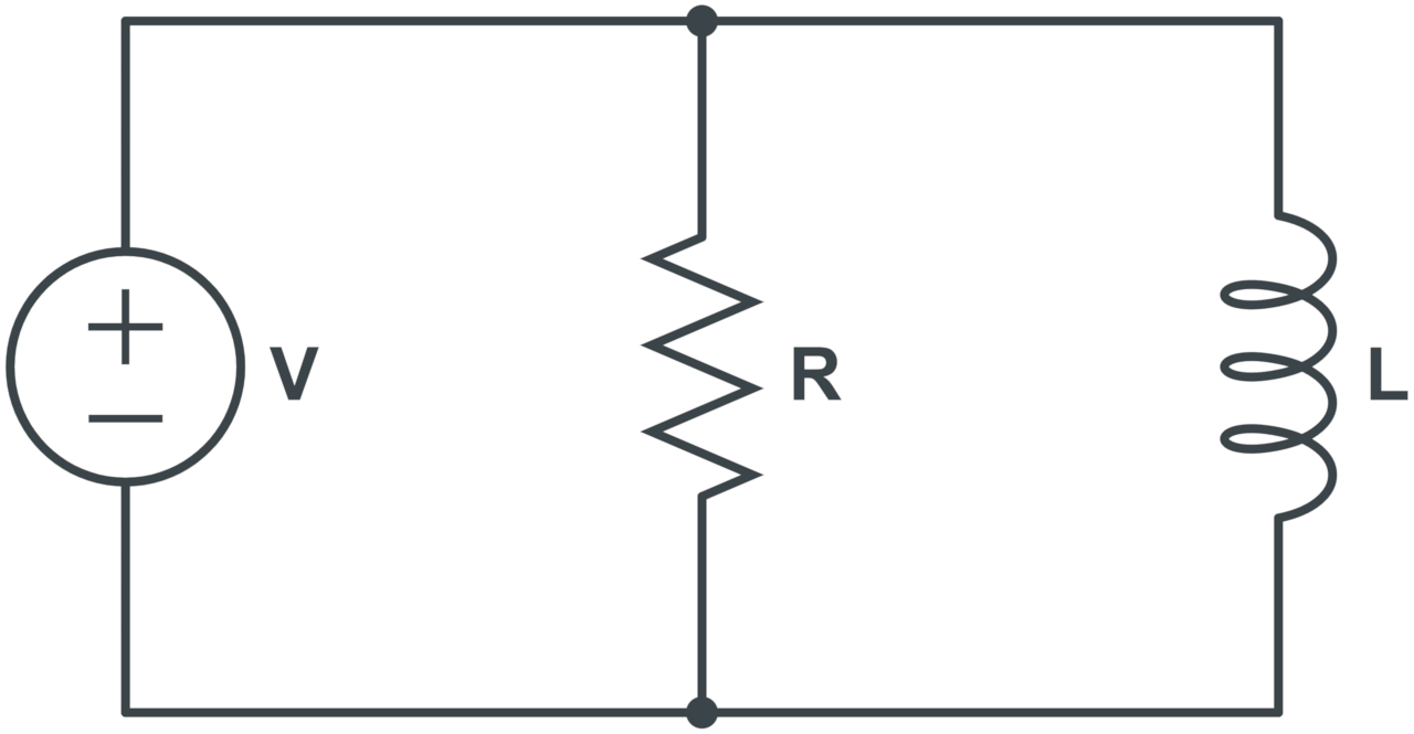
The formula to calculate the total impedance in parallel RL circuits is:
Where:
Z = impedance in Ω
R = resistance in Ω
L = inductance in H
ω = angular frequency in rad/s
The total impedance Z in Ohms for a parallel RL circuit is equal to the square root of the reciprocal of the resistance R in Ohms squared plus the reciprocal of the inductive reactance squared.
RC Impedance Formulas
RC circuits are circuits with a resistor and capacitor. You can use the following formulas to calculate the impedance for RC circuits in series or parallel.
Series RC Circuit Impedance Formula
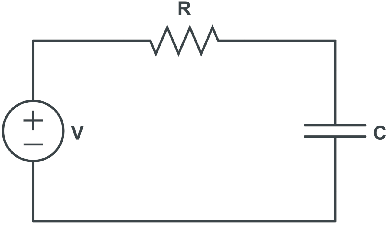
The formula to calculate the total impedance in series RC circuits is:
Where:
Z = impedance in Ω
R = resistance in Ω
C = capacitance in F
ω = angular frequency in rad/s
The total impedance Z in Ohms for a series RC circuit is equal to the square root of the resistance R in Ohms squared plus the capacitive reactance squared.
Parallel RC Circuit Impedance Formula
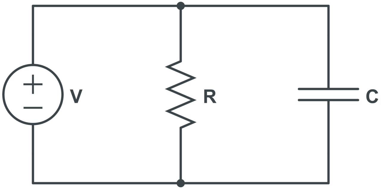
The formula to calculate the total impedance in parallel RC circuits is:
Where:
Z = impedance in Ω
R = resistance in Ω
C = capacitance in F
ω = angular frequency in rad/s
The total impedance Z in Ohms for a parallel RC circuit is equal to the square root of the reciprocal of the resistance R in Ohms squared plus the reciprocal of the capacitive reactance squared.
LC Impedance Formulas
In an LC circuit, where an inductor and a capacitor are connected in series or parallel, the impedance solely depends on the inductive and capacitive reactances since there is no resistive component.
Series LC Circuit Impedance Formula
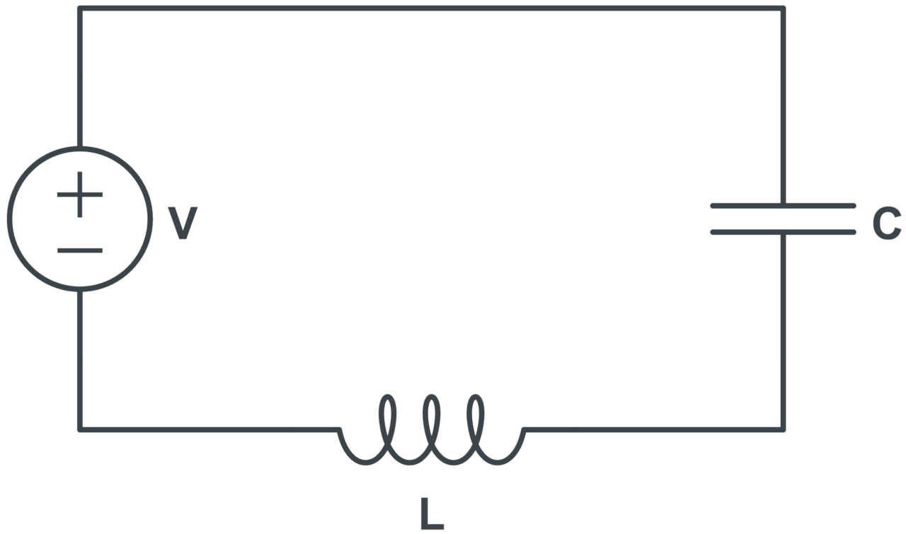
The formula to calculate the total impedance in series LC circuits is:
Where:
Z = impedance in Ω
L = inductance in H
C = capacitance in F
ω = angular frequency in rad/s
The total impedance Z in Ohms for a series LC circuit is equal to the absolute value of the inductive reactance minus the capacitive reactance.
Parallel LC Circuit Impedance Formula
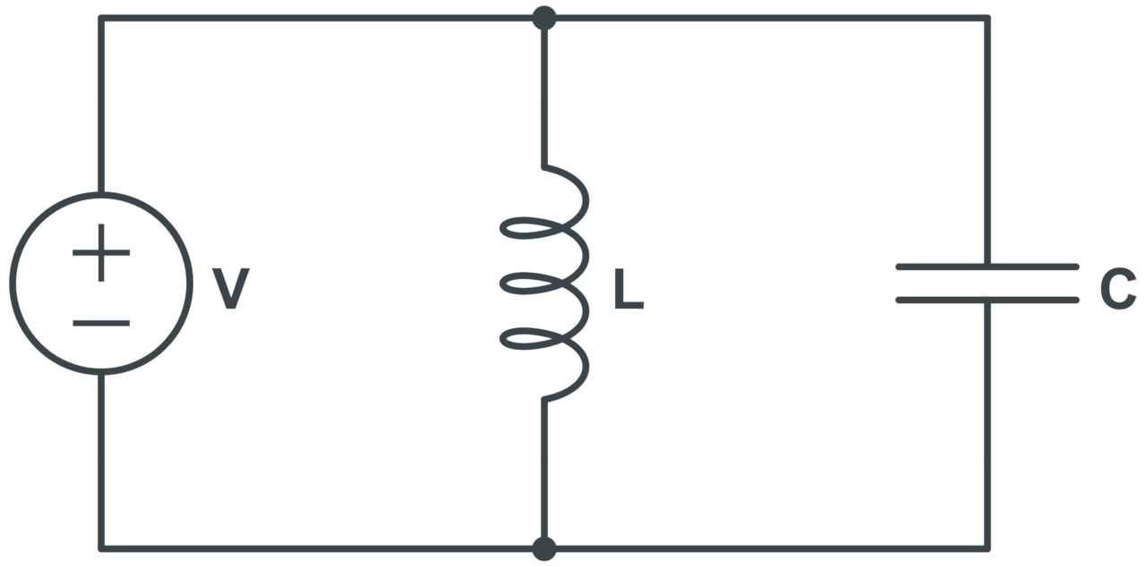
The formula to calculate the total impedance in parallel LC circuits is:
Where:
Z = impedance in Ω
L = inductance in H
C = capacitance in F
ω = angular frequency in rad/s
The total impedance Z in Ohms for a parallel LC circuit is equal to the reciprocal of the absolute value of the reciprocal of the inductive reactance minus the reciprocal of the capacitive reactance.